Updated 15 Dec 2009
|
WIRKSWORTH Parish Records 1600-1900
|
|
The Switchback at Matlock Bath 1889-1934
|
The infamous "Switchback" at Matlock Bath, enlarged from photos
X325, X345 and
X391.
Declared to be the "longest in the country" (it was 139 yards long).
Unfortunately it attracted the wrong kind of clientele to "couth"
Matlock Bath, and was not liked by many locals who could remember
the "Switzerland of England". It was described as "a wanton outrage
to one of the fairest scenes in England."
It was run by Herbert Buxton, who can be traced in the Census aged 8-68:
1841,
1851,
1861,
1871,
1881,
1891,
1901,
Buxton bought the Switchback from J.D.Bratby of Derby by
auction on 27 Sep 1889,
but ran into rate-paying problems in Apr 1890.
On a good Bank Holiday he is supposed to have used a wheelbarrow
to get his takings home.
A 1922 detailed map showing the exact position of the
switchback is shown below.
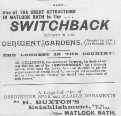
Dr Cullimore's advice to take half-a-dozen
rides to benefit one's liver sounds very suspicious.
The Switchback was opened in 1889 and was dismantled in 1934.
It was a close copy of Thompson's Gravity Switchback Railway, opened
5 years earlier in Coney Island. See
How it Works in a detailed
description in Thompson's Patent dated 1885.
See also A brief history and list of early
Switchbacks, and images of a
Swichback in Glasgow in 1888
|
From an advert for Derwent Gardens.
|
From a Notice Board in Derwent Gardens in 2007.
Derwent Gardens is the result of the combination of two areas, the Ferry
Grounds and the Orchard Holme. The Ferry Grounds was an area round the
landing stage. This area had been an important feature of Matlock Bath
life since the 1750's as the landing stage for the ferry and later for
boating and swimming events.
Orchard Holme was a meadow area next to the Ferry grounds. Here several
thermal springs bubble out of the ground and run into the river. Herbert
Buxton, a local businessman, bought the site in 1880 and developed an
amusement park to cater for day trippers whose numbers had increased once
the railway opened in 1849. A gravity powered roller coaster called the
'Switchback' was opened amidst great excitement in 1889.
The Ferry Grounds were landscaped in association with the building of the
Kursaal (now known as the Pavilion), by the local authority, who had
purchased the site for the building in 1908. The Orchard Holme was not
bought by Matlock Urban District Council until 1951. The amalgamation of
these two areas produced Derwent gardens which became the new home for
the annual illuminations in 1968 when the A6 road widening scheme removed
the Promenade Gardens, home to the event for seventy years.
|
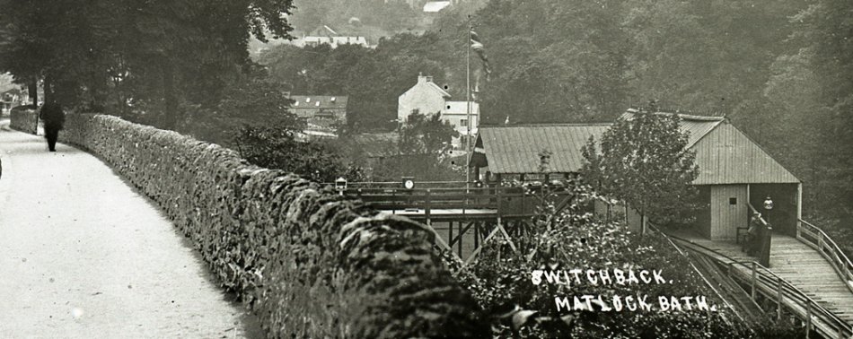
The entrance to the Switchback from South Parade opposite the Royal Hotel,
through a gateway in the stone wall, down 24 steps, and along a wooden
trestle walkway past at least 4 slot machines to the kiosk where you paid.
The man on the far right is thought to be Edgar Buxton (born 1881, an
auctioneer), son of the proprietor Herbert, next to a gaslight globe.
A flag is usually flying. The gauge is probably 2 ft 6 in, and the return
track climbs the final slope and meets again with the outgoing track just
behind Edgar.
|
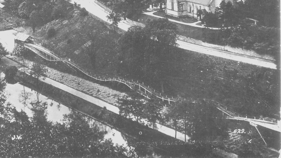
The whole run of the Switchback in Derwent Gardens, you started from
the shed on the right and turned round at the shed on the left.
|
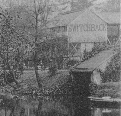
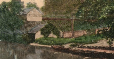
Enlargement from the tinted postcard below. The tinting has altered some
of the detail. A switchback car can be seen near the left shed.

|
Enlargement from a card posted in 1906, showing the
Southern end of the Switchback on its wooden trestles, and the
river-side track.
 |
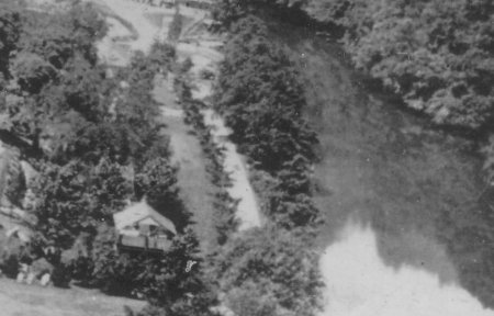
Enlargement from a card posted in 1910, showing the
Southern and Northern ends of the Switchback, the track running
between the trees, and the River Derwent on the right.
 |
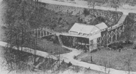
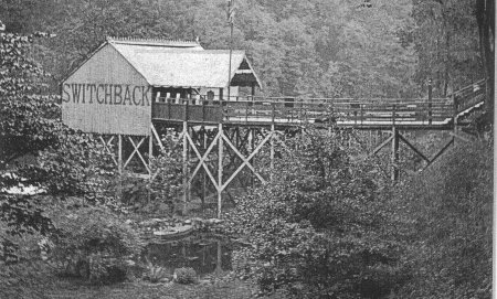
Detail from a card posted 24 Apr 1904. A novelty card, it has cutouts
where windows are, when held up to the light it looks like a night scene.
There are 2 cutouts in the word "Switchback" and 3 in the side facing
the reader. The wooden structure is well shown.
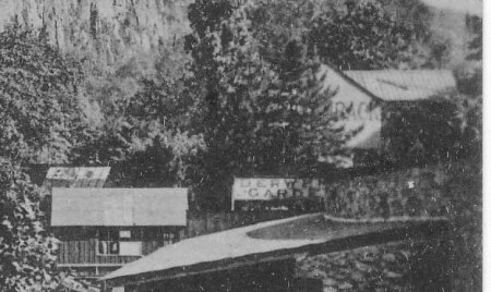
Enlargement from X348b. "Switchback" and
"Derwent Gardens" peep between the trees.
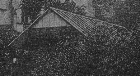
Enlarged from X336b posted 1905. A view of the
departing shed from across the river
Enlarged from X185b posted 1912. A view of the
departing shed from across the river.
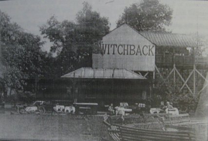
View of the departing shed, perhaps c1920. The low near-circular
wall held an open-air eating area with tables and chairs.
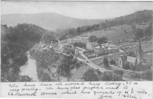
Taken 1886 by Francis Frith, 3 years before the Switchback was opened.
This card was posted 1905, but was printed before Sep 1902 (it has an
undivided back). A similar view, better known, was also taken in 1886
by Frith a minute before or after this picture. The horse is still
feeding, but people have walked further along the road, and a horse
and cart appears at the road junction.
|
An earlier (c1900?) view of the SWITCHBACK starting shed and the high-level
pedestrian walkway leading into it from the Promenade. The shed
extension has not yet been built, and pleasure rowing boats are moored
close by. A small barn, stone wall and five bar gate are shown which
later disappeared.
The starting shed in Derwent Gardens, with steps down from the
Promenade. On the side in large letters it reads "SWITCHBACK".
People queue outside and at the top of the steps. Others wait to board.
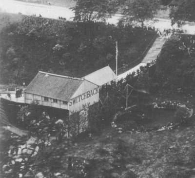
The half-way shed in Derwent Gardens.
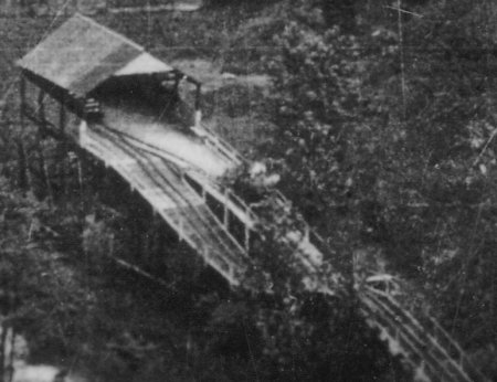
The starting shed, taken c1910 (original in LSL, Matlock)
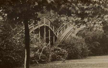
A glimpse of the switchback track through the trees of Derwent Gardens.
Matlock Register, Friday April 26th 1889
Good Friday and Easter Week
It will thus be seen that Matlock Bath was very busy indeed, and
doubtless the caterers retired to rest
after the two days' work tired but happy. Unusual attractions are
provided this season - a switch-back
railway, steam roundabouts and land sailors, shooting galleries,
and hosts of other things.
Matlock Register, 10th May 1889
Matlock Bath Local Board.
On Tuesday night the annual meeting of this board was held, when all
the members except
Mr Tyack were present...
Mr C.A.Peters was appointed chairman and
Mr Lennox vice-chairman.
The Clerk said they had no control over the recently-erected
switchback railway.
Mr J.W.Wheatcroft hoped the switchback
would be rated, and the proper authorities would see to the matter......
|
The Derby Mercury, 18 Sep 1889
MATLOCK BATH, DERBYSHIRE
TO BE SOLD BY AUCTION
By Messrs J and W HEATHCOTE
(By instructions from the Owner, Mr J D Bratby), at
the DEVONSHIRE HOTEL, Matlock Bath, on FRIDAY,
September 27th, 1889, at 6 for 7 o'clock in the Evening
prompt.
All that Valuable and Desirable Investment, the
Newly-erected SWITCHBACK RAILWAY, to
be sold as a going concern, in one lot, including Railway,
Three Cars, Turnstile, and all connected with it
as it now stands. Immediate possession can be had,
FREE OF ROYALTIES.
Further particulars and cards to view the same can
be obtained from the AUCTIONEERS, The Mart,
Exchange Buildings, Derby, or of the Owner, 44, Siddals
Road, Derby.
No DRAWINGS or TRACINGS of the same will be
permitted.
|
The Derby Mercury, 23 Apr 1890
THE MATLOCK BATH SWITCHBACK
The Matlock Bath Local Board sought to recover
£1 18s 4d, rates due
upon the assessment of the switchback railway, from the
proprietor, Mr H Buxton - Defendant contended that he
purchased the property, but did not become tenant
until Lady Day [25 March], and was not liable for rates
prior to that date. According to the poor rate
the property was declared void at the time the Local
Board levied. Mr Green, the clerk of the Board, said
great profits were made in the season upon the railway,
and next to nothing in winter. They did not assess upon
the profitable period, but for the whole year - Mr Dakin,
the collector, remarked that if this course was adopted
half the property in a watering place would be void and
pay no rates.- The Bench said they had no option in the
matter but to make an order - Mr Buxton: It is a piece
of nonsense; I shall have to appeal. - The order was made
returnable in a week, with costs.
|
|
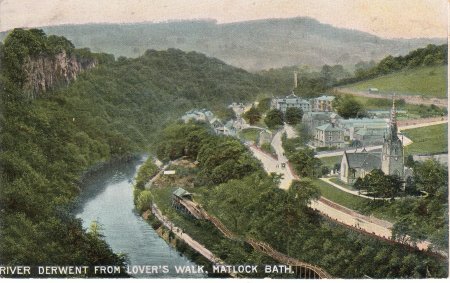
An aerial view of the position of the Switchback in Derwent Gardens,
but only half of the run can be seen on this postcard.
|
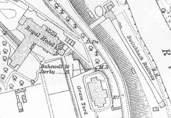
A scan from a 1922 O.S. map showing the position of the Switchback
in Derwent Gardens on the Banks of the River Derwent.
The map scale is 25.344" to a mile (208.33 ft to one inch),
the switchback outline is 2" long, giving a length of 139 yards,
claimed to be the longest in the country.
Thanks to the
Local Studies Library, Matlock.
|
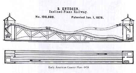
Knudsen's patent in 1878 (never built)
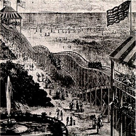
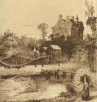
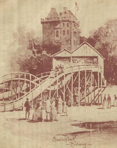
Thompson's Switchback in Coney Island,
Brooklyn, New York. Opened 1884
|
The first roller coasters were American. A lot of 19th century Switchback
history can be found on
Coaster History.
As early as 1878 Richard Knudsen patented the "Improvement in Inclined
Railways," (patent #128,674), but it never opened. Thompson patented
further improvements in 1885. From the old photos and an engraving,
the Matlock Bath switchback appears to be a close copy of Thompson's
Switchback in the USA, opened 5 years earlier, and is the same length.
Thompson added undulating
hills and the cars slowly (6 mph) rolled down a track six hundred feet
long and fifty feet high. The Switchback Railway opened in the spring of
1884 at Coney Island in Brooklyn, New York and made the inventor hundreds
of dollars per-day. Considering that Thompson only charged a nickel per-ride,
the success of the Switchback Railway is nothing short of amazing. History
has dubbed him the "Father of Gravity".
Wikipedia writes:
Thompson's Switchback Railway opened at Coney Island in 1884 and was the
first gravity-powered roller coaster built in the United States,
La Marcus Adna Thompson (March 8, 1848 - May 8, 1919 in Ohio, United States)
is best known for his early work developing roller coasters, and is
sometimes called the "Father of Gravity".
In 1827, a mining company in Summit Hill, Pennsylvania constructed the
Mauch Chunk gravity railroad, a 14-kilometre downhill track used to deliver
coal (and a miner to operate the mine train's brake) to Mauch Chunk Present
day Jim Thorpe, PA . By the 1850s, the "Gravity Road" (as it became known)
was providing rides to thrillseekers for 50 cents a ride. Railway companies
used similar tracks to provide amusement on days when ridership was low.
Using this idea as a basis, La Marcus Adna Thompson began work on a
closed-circuit switchback railway. His gravity ride opened at Coney Island
in 1884.
Wikipedia
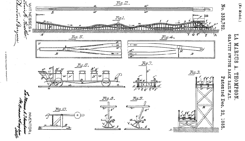
Thompson patented "Roller coasting structure" (US patent 310966) and
"Gravity switch back railway" (US patent 332762, see diagram below) in
Dec 1885.
|
Thompson's patent dated Dec 1885
|
United States Patent Office
La Marcus A. Thompson, of Philadelphia, Pennsylvania.
Gravity Switch-Back Railway.
Specification forming part of Letters Patent No.332,762, dated Dec 22, 1885
To all whom it may concern:
Be it known that I, LA MARCUS A.THOMPSON, of the city and county of
Philadelphia, in the State of Pennsylvania, have invented certain new and
useful Improvements in Gravity Switch-Back Railways, of which improvememnts
the following is a specification, reference being had to the accompanying
drawings, forming part hereof, in which-
Figure 1 is a side elevation of my improved switch-back railway, showing
the series of ascending and descending planes, the tunnel, and the starting
and terminal points within a pavillion. Fig.2 is a top or plan view of the
same. Fig.3 is a transverse section on an enlarged scale. Figs.4 and 5 are
respectively top or plan views, showing the automatic and sliding switches
and sections of rails at the respective ends of the railway-course. Fig.6
is a side elevation of a car in position, and such as has been found well
adapted for such puposes. Fig.7 is a cross-section of the car, showing the
peculiar construction of brake and mechanism for operating the same. Figs.
8 and 9 are respectively side elevations showing the brake in both its normal
and operative positions; and Fig.10 is a side elevation of the locking-dog
when not in use or while shifting it on the switches.
My invention relates to a gravity double-track switch-back railway to be used
as a source or means of pleasure and amusement; and it consists of certain
new and novel features, to be hereinafter more fully descibed, whereby
passengers may be carried from a certain starting-point at any convenient
or suitable elevation in a vehicle or car over a series of descending and
ascending longitudinal planes by the gravity momentum acquired by the car
in its passage over the planes to the opposite end of the course, and thence
to the terminal point, located within a pavillion or other suitable structure,
but, however, at a lower elevation than that of the starting-point therein,
thereby obviating all necessity for changing cars on the round trip, lessening
the time for making the trip, insuring greater safety to passengers riding
thereupon, and entirely obviating many serious and annoying features
existing in such structures as they have been heretofore constructed. The
car from the terminal point within the pavillion is elevated to the starting-
point therein by certain means and mechanisms, to be hereinafter fully
described.
A further feature of my invention is a novel construction of vehicle or
car for use in this connection, with mechanisms for controlling the
speed and for stopping the car ad libitum.
Referring to the drawings, A represents the ground or foundation upon
which the trestle-work B rests, preferably constructed of wood, but, if
deemed best for the purpose, may be constructed of iron, and in form
irregular or undulating, or consisting of a series of descending and
ascending longitudinal planes. Upon the top of this trestle-work,
forming the road-bed, are stringers c, c', c2 and c3 for the reception
of the rails d, d', d2 and d3, upon which the cars travel. Rigidly
secured to the road-bed of the trestle-work B, and just inside of each
pair of rail-stringers and in juxtaposition thereto, are the
guard-stringers e,e'and e2 and e3, made of any sutiable material,
but slightly higher than the rail-stringers, with narrow spaces f f'
between the respective stringers for the reception of the inside
projecting flanges, f2, of the car-wheels. These guard stringers prevent
the car-wheels in theirpassage over the series of descending and ascending
planes from jumping the tracks. Immediately inside of the guard stringers
e and e' and e2 and e3, and contiguous thereto, are the brake-stringers
g and g', g2 and g3, made, prefferably, of wood, for the car-brakes or
shoes V and V' to slide upon, andfor aiding in the stoppage of the vehicle
or car at any desired point or part of the course or railway.
F is a pavillion, either inclosed or open, of any suitable construction,
and of such height or elevation as may be desired, access to the elevated
starting-point i therein being had by a stair-case, i', from the ground A.
The passengers, having reached the elevated starting-point i within the
pavillion F, are seated in the car D. The car is then started down a slight
descending plane, k, to the summit l, passing over the same to the point m,
and collecting in its passage sufficient velocity or gravity momentum to
carry to and over the summit n, to descend with increased velocity over
the plane o, and thence mounting theascending plane p through an
automatically-working switch, S, to the end of the course. And when the
car is released from the locking-dog j at this end of the course T
it passes down over the tracks d and d' of the descending and ascending
planes, through a structure so constructed as to represent a tunnel, I,
to the terminal point q within the pavillion, but at a lower elevation than
that of the starting-point, discharging the passengers opposite to or aside
of the staircaseg', leading to the ground A. The car is then carried in any
convenient manner up the short ascending plane r, where it is held at
the summit r' by a locking-dog, j, rigidly secured to the trestle-work B,
whileshifting the car on the sliding switch R, as shown in Fig.4, to the
tracks leading to the starting-point i within the pavillion F. The car,
being released from the locking-dog j, rushes down the inclined plane r
far enough for the secondary cross-arm U' upon the under side of the car
to engage with a belt or chain, Q, carrying thereupon a series of hooks, t,
which chain or belt passes over a series of pulleys, t', having motion
imparted to them by gearing located in any convenient part of the structure
or pavillion and propelled by a steam-engine, Y, located either inside or
outside of the structure. The car, being elevated to the starting-point i
from the point s by means of the belt or chain Q, is released by the
attendent in charge of the brake-lever, and the car D is at once in
position for the reception of passengers for the next trip.
The car D - such as shown in Fig.6 of the drawings - is constructed of
stout material, preferably wood, with a series of seats, D', which may be
either reversible or rigid ones, having sides D2, made of similar material,
with openings W between the respective seats, for the admission of passengers.
Upon the tops of the sides D2 are hand-grips D3, securely fastened thereto.
The front and back ends of the car are provided with dash-boards D and G',
projecting outwardly therefrom. Immediately above the dash-board G' of the
car is a seat, G2, for the attendant in charge of the lever G3, actuating
the brake-shoes V V', having an arm, g4, projecting downward and rigidly
secured to the floor of the car D. Beneath the car D, beyond the back wheels,
is a cross-arm or shaft, U, held in bearings u u', rigidly attached to the
underside of the floor of the car. This cross-arm U has projecting from each
side thereof the brake-shoes V V', which brake-shoes are loosely secured to
the cross-arm U by collars w and w'. To the interior sides of these brakes
is riveted a secondary cross-arm, U'. By means of collars or sleeves z and z'
upon the cross-arms U and U' is secured the lever G3, for actuating the
brake-shoes V V'. This lever passes up through an oblong slot or opening,
z3, in the floor of the car, and then through guides z4 and z5, fastened
in any suitablemanner to the under side of the attendant's seat and the seat
of the car nearest thereto, for insuring the free movement of the lever
actuating the brake-shoes and for effecting the stoppage of the car at any
desired point, and if at any time occasion should arise for decreasing
the speed or gravity momentem acquired by the car in riding over the series
of descending and ascending planes of the course or railway.
Having thus described the nature and objects of my invention, what I claim
as new, and desire to secure by letters Patent, is-
- In a gravity switch-back railway, the combination, with the trestle-work
so constructed as to form a series of descending and ascending planes, of the
longitudinal stringers for the reception of the rails, the guard-ways or
stringers for preventing the cars from jumping the tracks, and the
brake-sliding ways or stringers, substantially as and for the purposes
described.
- In a gravity switch-back railway, the combination, with the undulating
trestle-work having thereon the longitudinal trackways and rails, of the
guard-stringers and brake-slide stringers contiguous thereto, of a car
having brake-shoes which engage with said brake-stringers through the
operationof a lever, substantially as and for the purpose set forth.
- In a gravity switch-back railway, the combination, with the undulating
trestle-work of the trackways and rails, of the guard stringers, of
brake-slide stringers, of the car-brakes actuated by a hand-lever, of the
automatic and sliding switches, of dogs for holding the cars, and mechanism,
substantially as described, for elevating the car from the plane r to the
starting-point, substantially as and for the purpose set forth.
- The combination, with a gravity switchback railway having starting
and terminal points at different altitudes, of the car D, provided with
brake mechanism consisting of shoes V V', cross-arms U U', and lever G2,
arranged and operating substantially as described.
LA MARCUS A. THOMPSON
Witnesses:
CHARLES F.ZIEGLER,
LOUIS H.KUELBER.
|
BRIEF HISTORY OF ROLLER COASTERS AND AMUSEMENT PARKS
|
Switchback Railways
2.1 The first ever purpose-built commercial roller coaster was constructed
in 1884 at West Tenth Avenue, Coney Island, Brooklyn, USA. It was called
the Switchback Railway, and was designed by an Indiana inventor named
La Marcus Thompson. By today's standards it would seem somewhat crude, and
it only ran at about six miles an hour. Robert Cartmell's book
The Incredible Scream Machine (1987, Amusement Park Books) describes it
as "little more than a scenic tour of the beach".
2.2 The ride consisted of tracks undulating over a wooden structure six
hundred feet long. A small train started at one end of the ride, about
fifty feet high, and ran in a straight line along the undulating track
until it got to the end. It was then 'switched' by the ride operators to
a return track which started off at a higher level, and took the rider back.
2.3 Within a few months, however, switchbacks were springing up everywhere,
including Britain. By 1885, only one year later, there was a switchback at
Skegness in the UK, Britain's first ever roller coaster. That was followed
by several others, including rides at Blackpool, Bridlington and Folkestone
(see Appendix 1 for a full list).
Scenic Railways and Figure Eights
2.4 Two other forms of roller coaster were quickly developed, which became
the mainstay of amusement parks around the world for the early part of the
20th Century: scenic railways and figure eights. In the UK, scenic railways
(from 1907) and figure eights (from 1908) often spelt the end for the
ageing switchbacks.
2.5 The roller coaster at Dreamland, Margate, is an example of a Scenic
Railway. The Scenic Railway roller coaster concept was also developed by
La Marcus Thompson. The first example opened in 1887 in Atlantic City, USA.
The idea behind the Scenic Railway was to create a ride where passengers
could enjoy an imaginary scenic tour. They featured articulated carriages,
powered cables to lift the trains up inclines, and often had their
structures covered by elaborate landscapes to create the effect of mountain
scenery. They were therefore the direct forerunner of the present modern-day
roller coaster. One major difference, however, is that the trains did not
have under friction wheels (used in modern day roller coasters to prevent
them from leaving the track), therefore they required the use of a brakeman
who sat between cars one and two keeping the speed in check. Scenic railways
became the most famous amusement ride in the world, and spread across the
globe to Britain, Europe and India.
Switchback Railways
Listed by town, name of park where known (dates in brackets)
Aberdeen (1886-1911)
Barry Island Pleasure Park (1897-1914, rebuild of Switchback from 1896 Cardiff Exhibition)
Birnbeck Pier, Weston-Super-Mare (date unknown)
Blackpool, Blackpool Pleasure Beach (1891-1922)
Blackpool, Raike's Hall (date unknown)
Blackpool, Rigby Road (date unknown)
Blackpool, St Chad's Drive (date unknown)
Blackpool, Uncle Tom's Cabin (date unknown)
Bradford Exhibition (1904)
Bradford, Shipley Glen (1887-1920)
Bridlington (1898-1912)
Brighton, Devil's Dyke (date unknown)
Burgess Hill (date unknown)
Cardiff Exhibition (1896)
Cleethorpes (1897-?)
Crystal Palace Exhibition (1889)
Douglas, Isle of Man (1887 approx-?)
Folkestone (?-1906)
Glasgow Exhibition (1888)
Glasgow Exhibition (1901)
Great Yarmouth (1887-1909, rebuilt at Honley, Huddersfield)
Honley, Huddersfield (1910-?, rebuild of switchback from Great Yarmouth)
Hull, White City Pleasure Grounds (date unknown)
Morecambe, Winter Gardens (date unknown)
Nottingham Exhibition (1903)
Ramsgate Pier (date unknown)
Saltaire Exhibition (1887)
Scarborough (1888-1905)
Skegness (1885-1911)
Southend-on-Sea, Marine Gardens (1894-?)
Southport (?, it was present in 1895)
South Shields, Ocean Pleasure Beach (?-1910)
Sutton Coldfield, Sutton Park (1906-1936)
|
Compiled, formatted, hyperlinked, encoded,
and copyright © 2006,
 All Rights Reserved.
|


 All Rights Reserved.